Hotline:


DAHUSI
PRODUCTS

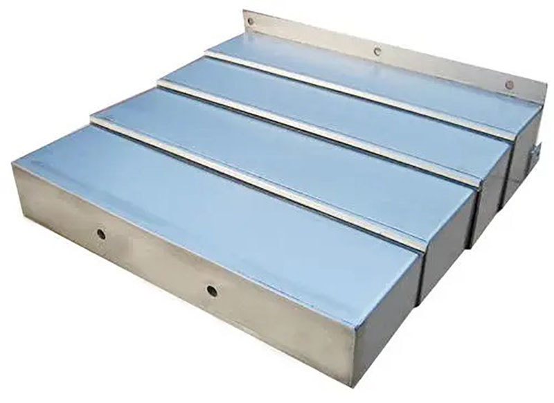
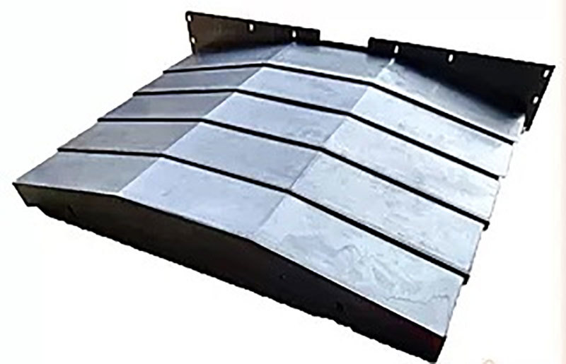
Steel plate protective cover
Classification:
Details


|
Parameter Code |
Parameter Name |
Parameter Value |
Description |
Remarks |
Test Results |
|
Lmax |
Maximum extension of the protective cover |
|
Operating range of the machine tool (required) |
|
|
|
Lmin |
Minimum extension of the protective cover |
|
|
|
|
|
S |
Protective cover stroke |
|
Maximum stroke of the machine tool (optional) |
|
|
|
W |
Outer width of the protective cover |
|
Required |
|
|
|
Wi |
Inner width of the protective cover |
|
Required |
|
|
|
W0 |
Minimum height |
|
Optional |
|
|
|
h |
Outer height of the protective cover |
|
Required |
|
|
|
h1 |
Inner height of the protective cover |
|
Required |
|
|
|
d |
Distance between guide rail centers |
|
Required |
|
|
|
d1 |
Distance from end plate to guide rail |
|
Required |
|
|
|
|
Accessory Selection |
|
Optional |
|
|
|
|
Protective cover material |
|
Material/Surface treatment (optional) |
|
|
|
|
Guide rail Model |
|
Model or Size (with drawing) Required |
|
|
|
|
Machine tool operating speed |
|
Required |
|
|
|
|
Installation method |
|
Horizontal/Vertical/Others (optional) |
|
|
|
|
Installed machine Model |
|
Optional |
|
|
|
|
Operating environment |
|
Is there a large amount of debris? (optional) |
|
|
|
Ordering unit |
|
Delivery Address |
|
||
|
Contact information |
|
Delivery method |
Air freight, Land transport, Express delivery, Others: |
||
|
When ordering, please provide the above data, CAD drawings, or 3D drawings of the machine tool (.stp/.x-t/.igs format, etc.) so that we can evaluate and design. If you have special requirements for the ordered protective cover, please fill in the remarks column or contact our company directly; if there are no requirements, it will be made according to our company's standards. For the design of partial protection of the guide rail, please provide detailed drawings. If the ordering party provides a complete protective cover drawing, please indicate whether there is a margin between the protective cover and the guide rail. We will send this form with the product upon delivery. |
|||||
This form can be downloaded by the customer.
Other Products
Product Consulting
Hello!
Thank you for visiting Dahusi's official website. If you have any cooperation intention or suggestions, please contact us through the following ways, and we will give you feedback in time. Thank you!
Address: No. 236 Jietai Road, Digital & Intelligent Industrial Park, Banan District, Chongqing
Zip Code: 400055

Mobile Version

Official Account

Applet
Copyright©2025 Chongqing Dahusi Precision Machinery Manufacturing Co., Ltd.


- Phone 86-23-66287188
- Phone
- Message
- TOP